


 Individual games
  Functional play
  Speed
Speed  Altitude experience
  Technical Drawing (3D)
  Download all files
 Brief description
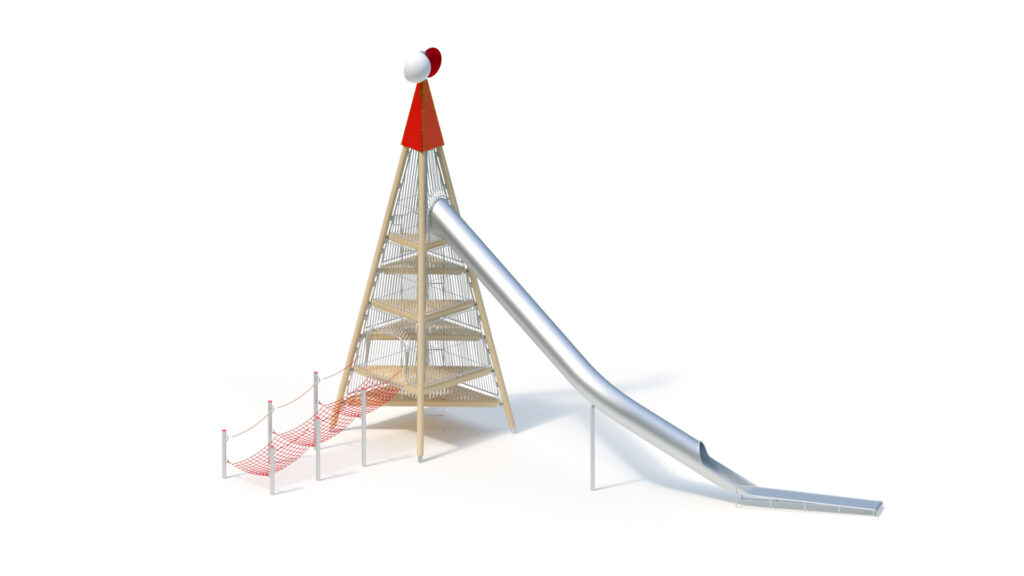
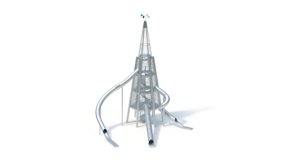
Dalben tower (20,00) with tunnel slide, helical tunnel slide and roller slide
A. Dalben tower
Technical data
Area: 15,00 x 18,20 m
Minimum space: 18,50 x 21,50 m (278 m²)
Total height: 19,96 m
Platform heights: 3,00 / 6,00 / 9,00 m
Slide installation heights: 3,00 / 6,00 / 9,00 m
Slide entrance heights: 3,10 / 6,10 / 9,10 m
Posts
Tubular steel, Ø 355 mm, hot-dip galvanised
Platforms
Stainless steel platforms, welded construction with lug pattern, glass bead blasted, screw-fitted flange fixing to posts
Access
spiral staircase up to platform height 9,00 m, Ø 1,90 m with stainless steel steps, protective barriers and balustrades from stainless steel, glass bead blasted
Protective barriers
upwards from platform height 3,00 m, welded structure made of stainless steel tubes Ø 21,3 / 48,3 mm, with handrail, glass bead blasted, screw-fitted flange fixings at platforms.
Cross bracing M20 System mconnect, DIBT license No. Z-14.4-441 according to DIN 18800: hot-dip galvanised fork heads from quenched and tempered steel casting. Tension rods from high-strength fine-grained structural steel S460N.
Tower roof
Height: 12,00 m
Stainless steel roof with opal dome light Ø 2,00 m, welded structure, glass bead blasted, screw-fitted flange fixings at posts
Tower top
Tubular construction from stainless steel Ø 20/90 mm, glass bead blasted; screw-fitted flange fixings at posts (top ends furnished with protective stainless steel caps)
Top element
Two-piece wind rotor, Ø 500 mm with powder-coated half shells made from stainless steel, mounted to an anti-friction bearing
Anchorage
Dowelling of each base plate by means of 6 stainless steel injection anchors, material specification A4.
As damage protection, the tower is equipped with a lightning conductor.
B. Roller slide (3,00)
Installation height: 3,00 m
Entrance height: 3,10 m
Slide inclination: approx. 15°
Diameter of tunnel section: 0,96 m
Diameter of the sliding rollers: 50 mm
Sliding sheet metal thickness: 2,5 mm
Roller slide, length 15,00 m, straight, with light domes.
Roller slide sections with interior handrail guideway made from stainless steel, one-piece welded assembly.
Grip openings on both sides of the entrance section. Light domes made from break-proof Polycarbonate.
Stainless steel rollers mounted to anti-friction bearings.
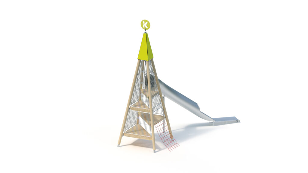
C. Helical Tunnel slide (6,00)
Installation height: 6,00 m
Entrance height: 6,10 m
Slide inclination: 30°/38°
(Clockwise) helical course: 360°
Diameter of tunnel section: 0,80 m
Sliding sheet metal thickness: 2,5 mm
Centre pylon made from tubular stainless steel: Ø 298,5 x 7,1 mm, stainless steel sheet coating Ø 313 x 2,5 mm
Sliding sections from stainless steel, of low noise level thanks to trough shape, slide in three parts, including appropriate connecting flanges to facilitate installation on site.
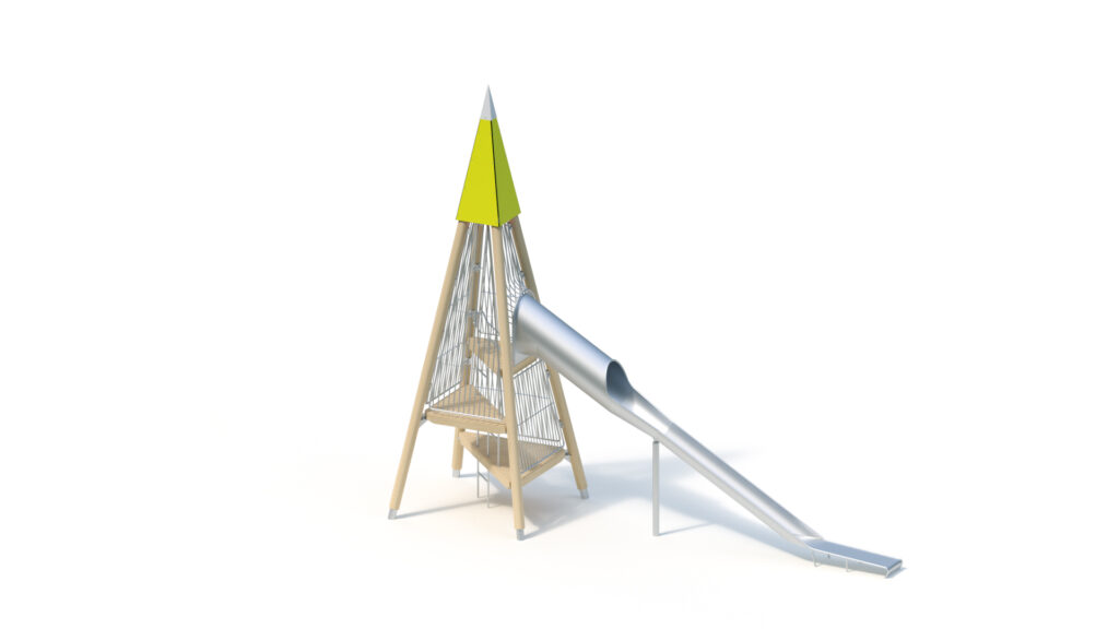
D. Tunnel slide (9,00)
Installation height: 9,00 m
Entrance height: 9,10 m
Slide inclination: 30°/36°
Diameter of tunnel section: 0,80 m
Sliding sheet metal thickness: 2,5 mm
Tubular stainless steel support post Ø 120 x 3 mm
Sliding sections from stainless steel/Light domes made from break-proof Polycarbonate, of low noise level thanks to trough shape, slide in three parts, including appropriate connecting flanges to facilitate installation on site.
Course: 25° curve to the right, 105° curve to the left
Including K&K Tunnel slide support posts made from tubular stainless steel Ø 120 x 3 / 159 x 4 mm with stainless steel fastening flange.
Foundations (on site)
6 pcs. 1,20 x 1,00 x 0,90 m
3 pcs. 0,60 x 0,60 x 0,60 m
5 pcs. 1,00 x 0,40 x 0,40 m
1 pc. 0,80 x 0,80 x 1,00 m
3 pcs. 1,00 x 0,40 x 0,40 m
1 pc. 1,20 x 0,40 x 0,40 m
concrete amount: 9,24 m³
The foundation sizes indicated in this quotation correspond to static requirements for soils with moderate solubility with an admissible footing pressure of at least σR,d = 180 kN/m² for towers with six posts.
With a deviating soil characteristic or with installation in areas with a high wind load (differing from wind zone 2 in Germany, equates to vref = 25,0 m/s) or with a high snow load (differing from snow load zone 2 in Germany, equates to sk ≥0,85 kN/m²), technical modifications of the product construction might become necessary (for instance the addition of cross bracings). Thereby, additional costs and the extension of the delivery time will arise.
Upon request of the customer, Kaiser & Kühne can engage a recognised engineering office to establish the necessary static calculation. The customer must bear the costs arising hereby. Any necessary evidence of the local conditions must be provided by the customer.
 Sales partner search
  Make contact